

- 商品详情
Product applicable environment
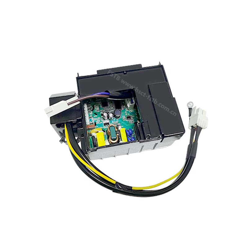
DC 12V/24V variable frequency drive controller • Maximum input power 80W system
1.Application
DC inverter compressors, it mainly used in portable refrigeration systems, micro-refrigeration systems, temperature-controlled shipping containers, electronic refrigeration systems, medical imaging systems, mini cooling water systems, and the cooling of outdoor communication base stations and communication cabinets.
2.Product Advantages
• Universal
This product adopts advanced circuit design technology and PCB Layout technology. This product has a unique technology, the compressor drive control parameters are independent of the application software, the user only needs to update the control parameters to change the compressor, and the electronic control and drive hardware do not need to be changed.
• Intelligent This product has the function of frequency hopping. By presetting the frequency hopping point, the related problems caused by the resonance point can be easily avoided.
• High reliability
This product is designed in accordance with UL relevant standards to ensure first-class quality. At the same time, comprehensive and multi-dimensional (voltage, current, environmental and load conditions) exceed the actual application conditions to test. This product has a variety of protection functions (overcurrent, overvoltage, overtemperature, overpower, phase loss, locked rotor, etc.), and key protections such as output overcurrent protection are controlled by software and hardware dual protection strategies.
• high efficiency
This product adopts high-performance digital signal processor, sensorless vector control algorithm based on resistance sampling and extended back electromotive force, and realizes the efficient operation of the drive system. This product adopts a unique hybrid pulse width modulation technology to improve the overall operating efficiency of the driver on the basis of weighing noise and efficiency. Compared with the traditional continuous wide modulation technology, the switching loss of this product is reduced by 50%.
4.Application Function

In the above picture, the blue background shows this product, which is packaged in a plastic box and has 8 external interface terminals. ①~⑧ in the above picture are external accessories, as shown below:
① Indicates external DC power supply, this product is 12V/24V compatible;
② Indicates an external fuse, of which 15A fuse is recommended for 12V system, and 7.5A fuse is recommended for 24V system;
③ Indicates an external DC power switch, which is used to control the power supply of the entire product;
④ Indicates an external light-emitting diode, which is used to indicate the operating status and fault of the controller;
⑤ Indicates an external DC fan, which acts as a condensing fan for the entire cooling system and dissipates heat for the controller at the same time;
⑥ Indicates a temperature control switch, which can be used as the exhaust over-temperature protection of the compressor;
⑦ Indicates adjustable resistance, which is used to adjust the running speed;
⑧ Indicates a fixed resistance value resistor, which is used to select the working voltage; Refer to the following for the parameters and detailed descriptions of the product port and each external unit.
5.Specification
# | Item | unit | value | comments |
1 | Max. input power | W | 80 | |
2 | Rated voltage | Vdc | 24/12 | Selected by external resistor |
Max. operate DC current | Vdc | 31.5 @ 24V input | ||
3 | 17 @ 12V input | |||
4 | Max. operate temp. | ℃ | 60 | |
Max. output current | Arms | 5 @24V input | ||
5 | 10 @12V input |

Terminals
# | Terminal | model | function | comments |
1 | - | 187 flag type terminal | DC power | Controller adaptive 24V/12V power input |
2 | + | DC power | ||
3 | F+ | DC fan | The controller supports 12V DC fan, the maximum output current is 0.5A, that is, the fan power does not exceed 6W | |
4 | F- | DC fan | ||
5 | D | Indication light | The LED current does not exceed 10mA, please refer to the following instructions for instructions; | |
The positive terminal of the LED is directly connected to the positive terminal of the power supply | ||||
6 | C | Public control | Connect the temperature control switch at the < C > and < T > ends; | |
adjustable resistor is connected in series in the middle to adjust the running speed of the compressor; | ||||
When the adjustable resistor is not connected (shorted), the default running speed is 2000rpm | ||||
(refer to 2-1)。 | ||||
7 | P | Voltage protection setting | Voltage protection threshold setting terminal, through this connection between < C >-< P > | |
(refer to 2-1)Resistor sets the voltage protection threshold, refer to Table 5-2 for details | ||||
8 | T | Temp. switch connection | Refer to the diagram | |
9 | U V W | Compressor connection | Air connection, pay attention to the line sequence, refer to the diagram |

4-1 Terminal connection diagram
6.Function details
As mentioned above, through the adjustable resistance connected between the terminals < T > and < C > (refer to ⑦ in Figure 2-1), different operating speeds are set, with a total of 16 gears, each gear differing by 100rpm. The resistance-speed settings are shown in the table below:
<T>-<C> resistance | <T>-<C> current | Compress speed | ||
# | (Ω) | (mA) | (RPM) | remark |
1 | 0 | 3.4 | 2000 | The default running speed, if no adjustable resistance is connected between T and C, when the temperature control switch closes the loop, it will run at this speed |
2 | 51 | 3.2 | 2100 | |
3 | 100 | 3 | 2200 | |
4 | 150 | 2.9 | 2300 | |
5 | 200 | 2.8 | 2400 | |
6 | 277 | 2.6 | 2500 | |
7 | 330 | 2.5 | 2600 | |
8 | 400 | 2.4 | 2700 | |
9 | 490 | 2.2 | 2800 | |
10 | 586 | 2.1 | 2900 | |
11 | 692 | 1.9 | 3000 | |
12 | 816 | 1.8 | 3100 | |
13 | 963 | 1.7 | 3200 | |
14 | 1137 | 1.5 | 3300 | |
15 | 1331 | 1.4 | 3400 | |
16 | 1523 | 1.3 | 3500 | |
17 | >3000 | downtime |
Note:
(1). The resistance-speed comparison table is closely related to the compressor, and different compressors are slightly different. Please contact our company for details.
(2). At the same time, this drive control product has the function of frequency hopping, and the specific frequency hopping point can also be set. Please contact our company for details.
Voltage protection function
This product is automatically compatible with DC 24V/12V input. In order to protect the power supply, different undervoltage protection thresholds can be set through external fixed resistors between < P > and < C > (refer to Figure 2-1). The specific correspondence is as follows The table shows:
# | Ext. resistance | rated 12V | rated 24V | ||||||
(P-C) | Under voltage protection | Over voltage protection | Under voltage protection | Over voltage protection | |||||
(kΩ) | Stop value | Recover value | Stop value | Recover value | Stop value | Recover value | Stop value | Recover value | |
1 | 0.82 | 8.5 | 9.8 | 16 | 17 | 21.3 | 22.7 | 29.5 | 31.5 |
2 | 1.6 | 9.7 | 11 | 16 | 17 | 21.5 | 22.9 | 29.5 | 31.5 |
3 | 2.4 | 9.9 | 11.2 | 16 | 17 | 21.8 | 23.2 | 29.5 | 31.5 |
4 | 3.6 | 10 | 11.3 | 16 | 17 | 22 | 23.4 | 29.5 | 31.5 |
5 | 4.7 | 10.1 | 11.4 | 16 | 17 | 22.3 | 23.7 | 29.5 | 31.5 |
6 | 6.2 | 10.2 | 11.5 | 16 | 17 | 22.5 | 23.9 | 29.5 | 31.5 |
7 | 8.2 | 10.4 | 11.7 | 16 | 17 | 22.8 | 24.2 | 29.5 | 31.5 |
8 | 11 | 10.5 | 11.8 | 16 | 17 | 23 | 24.4 | 29.5 | 31.5 |
9 | 14 | 10.6 | 11.9 | 16 | 17 | 23.3 | 24.7 | 29.5 | 31.5 |
10 | 18 | 10.8 | 12.1 | 16 | 17 | 23.6 | 25 | 29.5 | 31.5 |
11 | 24 | 10.9 | 12.2 | 16 | 17 | 23.8 | 25.2 | 29.5 | 31.5 |
12 | 33 | 11 | 12.3 | 16 | 17 | 24.1 | 25.5 | 29.5 | 31.5 |
13 | 47 | 11.1 | 12.4 | 16 | 17 | 24.3 | 25.7 | 29.5 | 31.5 |
14 | 82 | 11.3 | 12.6 | 16 | 17 | 24.6 | 26 | 29.5 | 31.5 |
15 | >220 | 8.5 | 9.8 | 29.5 | 31.5 | ||||
Fault indication function
As shown before, connect an LED with a rated current of less than 10mA to the terminals < D > and < + > for fault indication. The anode of the LED is connected to the < + > terminal of the control, and the cathode is connected to the < D > terminal of the control. When a fault occurs, the LEDs cycle at 3 second intervals, blinking continuously on each cycle. Flashing different times according to different faults, each flashing is 0.4 seconds, continuous flashing for 3.2 minutes. The specific faults and flicker comparison are shown in the following table:
# | Flash times | Fault define | Fault desc |
1 | 1 | Unusual input voltage | The input voltage is outside the setting range |
2 | 2 | Fan fault | Fan current terminal output current is greater than 1A or open circuit |
3 | 3 | Compressor start fault | The compressor motor is blocked or the system pressure difference is too large (>6kg) |
4 | 4 | Compressor min. speed fault | The compressor load is too large or the compressor motor speed is too small |
5 | 5 | Over temp.. Protection | Controller case temperature is too high (>85°C) |
6 | 6 | Hardware fault | The controller detects an abnormal parameter |